Warning: This document is an unpublished work under development and shall not be referred
to as a SMPTE Standard,
Recommended Practice, or Engineering Guideline. It is distributed for review and comment; distribution does not constitute
publication. Recipients of this document are strongly encouraged to submit, with their comments, notification of any relevant
patent rights of which they are aware and to provide supporting documentation.
The Society of Motion Picture and Television Engineers (SMPTE) is an
internationally-recognized standards developing organization. Headquartered
and incorporated in the United States of America, SMPTE has members in over
80 countries on six continents. SMPTE’s Engineering Documents, including
Standards, Recommended Practices, and Engineering Guidelines, are prepared
by SMPTE’s Technology Committees. Participation in these Committees is open
to all with a bona fide interest in their work. SMPTE cooperates closely
with other standards-developing organizations, including ISO, IEC and ITU.
SMPTE Engineering Documents are drafted in accordance with the rules given
in its Standards Operations Manual.
At the time of publication no notice had been received by SMPTE claiming patent
rights essential to the implementation of this Engineering Document.
However, attention is drawn to the possibility that some of the elements of this document may be the subject of patent rights.
SMPTE shall not be held responsible for identifying any or all such patent rights.
This document was prepared by Technology Committee 35PM.
The following summarizes the changes from the previous edition of this document:
This specification defines IMF Application #2E. It is a specialization of the IMF Framework. Application #2E is meant for studio applications where a TV or movie title is transformed into multiple content versions (airline edits, special edition, languages...) that are made available to multiple consumer distribution channels (Internet, optical media, broadcast...) across multiple territories and over the span of many months to over a year. It uses image essence coded as a JPEG 2000 codestream and audio essence coded as linear PCM.
The following documents are referred to in the text in such a way that some or all of
their content constitutes requirements of this document. For dated references, only the edition cited
applies. For undated references, the latest edition of the referenced document
(including any amendments) applies.
SMPTE ST 377-1:2011, Material Exchange Format (MXF) - File Format Specification
SMPTE ST 379-1:2009, Material Exchange Format (MXF) - MXF Generic Container
SMPTE ST 422:2019, Material Exchange Format - Mapping JPEG 2000 Codestreams into the MXF Generic Container
SMPTE ST 2067-2:2020, Interoperable Master Format - Core Constraints
SMPTE ST 2084:2014, High Dynamic Range Electro-Optical Transfer Function of Mastering Reference Displays
SMPTE ST 2086:2018, Mastering Display Color Volume Metadata Supporting High Luminance and Wide Color Gamut Images
SMPTE ST 2113:2018, Colorimetry of P3 Color Spaces
Recommendation ITU-R BT.601-7, Studio Encoding Parameters of Digital Television for Standard 4:3 and Wide-Screen 16:9 Aspect Ratios
Recommendation ITU-R BT.709-6, Parameter Values for the HDTV Standards for Production and International Programme Exchange
Recommendation ITU-R BT.2020-2, Parameter Values for Ultra-High Definition Television Systems for Production and International Programme Exchange
Recommendation ITU-R BT.2100-2, Image parameter values for high dynamic range television for use in production and international programme exchange
CTA 861-G, A DTV Profile for Uncompressed High Speed Digital Interfaces (November 2016)
IEC 61966-2-4 Edition 1.0, Multimedia Systems and Equipment - Colour Measurement and Management - Part 2-4: Colour Management - Extended-Gamut YCC Colour Space for Video Applications - xvYCC
ISO/IEC 15444-1:2019, Information Technology - JPEG 2000 Image Coding System: Core Coding System
ISO/IEC 15444-15:2019, Information technology - JPEG 2000 image coding system - Part 15: High Throughput JPEG 2000
ISO 11664-3:2012 (CIE S014-3/E:2011), Colorimetry - Part 3: CIE Tristimulus Values
World Wide Web Consortium (W3C) (2004, October 28). XML Schema Part 1: Structures (Second Edition)
Normative text is text that describes elements of the design that are indispensable or contains the
conformance language keywords: "shall", "should", or "may". Informative text is text that is potentially
helpful to the user, but not indispensable, and can be removed, changed, or added editorially without
affecting interoperability. Informative text does not contain any conformance keywords.
All text in this document is, by default, normative, except: the Introduction, the Bibliography, or any clause explicitly
labeled as "Informative" or individual paragraphs that start with "Note:"
The keywords "shall" and "shall not" indicate requirements strictly to be followed in order to conform to the
document and from which no deviation is permitted.
The keywords, "should" and "should not" indicate that, among several possibilities, one is recommended
as particularly suitable, without mentioning or excluding others; or that a certain course of action
is preferred but not necessarily required; or that (in the negative form) a certain possibility
or course of action is deprecated but not prohibited.
The keywords "may" and "need not" indicate courses of action permissible within the limits of the document.
The keyword "reserved" indicates a provision that is not defined at this time, shall not be used,
and may be defined in the future. The keyword "forbidden" indicates "reserved" and in addition
indicates that the provision will never be defined in the future.
A conformant implementation according to this document is one that
includes all mandatory provisions ("shall") and, if implemented, all recommended provisions
("should") as described. A conformant implementation need not implement
optional provisions ("may") and need not implement them as described.
Unless otherwise specified, the order of precedence of the types of normative information in
this document shall be as follows: Normative prose shall be the authoritative definition;
tables shall be next; then formal languages; then figures; and then any other language forms.
The XML schema root element shall be as defined in Figure 1
<xs:schema targetNamespace="http://www.smpte-ra.org/schemas/2067-21/2016"
    xmlns:app2e="http://www.smpte-ra.org/schemas/2067-21/2016"
    xmlns:xs="http://www.w3.org/2001/XMLSchema"
    elementFormDefault="qualified"
    attributeFormDefault="unqualified">
    <!-- schema definitions found in this document -->
</xs:schema>
Each image frame shall conform to one of the permitted combinations of image frame characteristics listed in Table 2.
The notation a..b indicates that any value between a and b, including a and b, is allowed. For instance, the range 1..4096 includes the value 3840 and the range 1..3112 includes the value 2160.
EXAMPLE 1An image frame that combines COLOR.6 colorimetry with Y'C'BC'R color components is not supported.🔗
EXAMPLE 2A monoscopic progressive R'G'B' 4:4:4 image frame with dimensions 3840x2160 that combines COLOR.7 colorimetry with 12-bit pixel bit depth, 60 Hz frame rate, and QE.2 quantization is supported🔗
NOTE 1 — This specification does not support the Y'CC'BCC'RC (constant luminance) color components specified in Recommendation ITU-R BT.2020-2.🔗
An image frame with interlaced structure shall consist of a pair of fields, a first field then a second field. The lines of each field shall have twice the vertical spatial sampling pitch of the frame. Lines in the second field shall be displaced vertically by the vertical sampling pitch and the line timing shall be delayed temporally by half the frame time from the lines in the first field.
The temporal order and relative line positions of the two fields are indicated by the Field Dominance and DisplayF2Offset items described in 7.2, Table 7.
Implementations shall support the color component of each pixel being represented by an integer in the set {0..2n - 1}, with n being the pixel bit depth.
In 4:4:4 sampling, each component shall be sampled once at each image frame pixel.
In 4:2:2 Y'C'BC'R sampling, the Y' component shall be sampled at each pixel, but the C'B and C'R components shall be horizontally subsampled by a factor of two with respect to the Y component, co-sited with evennumbered Y' samples
Monoscopic essence consists of a single sequence of image frames.
Stereoscopic essence consists of a sequence of pairs of image frames, a left eye frame and a right eye frame, for stereoscopic viewing. The two images of a pair shall be coincident in time.
R'G'B' components are mapped to Y'C'BC'R components using the (non-constant luminance) derivation of Y' and color difference signals specified in Table 4 of Recommendation ITU-R BT.2020-2.
COLOR.6
Mapped using the P3D65 color system color primaries and white point specified in SMPTE ST 2113:2018 and the transfer function specified in SMPTE ST 2084:2014
COLOR.7
R'G'B' components are mapped using the color primaries and white point specified in Recommendation ITU-R BT.2020 and the transfer function specified in SMPTE ST 2084:2014
R'G'B' components are mapped to Y'C'BC'R components using the (non-constant luminance) derivation of Y' and color difference signals specified in Table 4 of Recommendation ITU-R BT.2020-2.
R'G'B' components are mapped to Y'C'BC'R components using the (non-constant luminance) derivation of Y' and color difference signals specified in Table 4 of Recommendation ITU-R BT.2020-2.
NOTE — In Recommendation ITU-R BT.601-7 and Recommendation ITU-R BT.709-6, the signals R', G', B', Y', C'B and C'R are referred to as signals E'R, E'G, E'B, E'Y, E'CB and E'CR respectively, i.e. they correspond to gamma pre-corrected signals.🔗
Implementations shall support the combinations of JPEG 2000 profiles (as specified in ISO/IEC 15444-1:2019), constraints on HTJ2K Codestreams, and image frame dimensions listed in Table 5.
NOTE 1 —
See 6.2 for a definition of the notation a...b.
🔗
All allowed at a given Mainlevel with the exception of Sublevel 0
Sublevel 0 only
All allowed at a given Mainlevel with the exception of Sublevel 0
Sublevel 0 only
All allowed at a given Mainlevel with the exception of Sublevel 0
NOTE 2 — The JPEG 2000 Broadcast Contribution profiles do not support either 16-bit Pixel Bit Depth or a Maximum Components Sampling Rate greater than 520·106 samples · s-1. In both cases, JPEG 2000 IMF profiles are used instead.🔗
NOTE 3 — The JPEG 2000 profiles, operating level and sublevel in Table 5 are selected as described in Annex E🔗
NOTE 4 — The APP2.HT.REV or APP2.HT.IRV constraints are specified in Annex H.🔗
Example encoder commands that generate JPEG 2000 Part-1 and JPEG 2000 Part-15 (HTJ2K) codestreams that satisfy these constraints are included in Annex I.
In the case of progressive frame structure, the image essence shall be wrapped according to mode P1 specified in SMPTE ST 422:2019 ("Frame-wrapping").
In the case of interlaced frame structure, the image essence shall be wrapped according to mode I1 specified in SMPTE ST 422:2019 ("Interlaced Frame, 1 field per KLV Element")
The Top-Level File Package of Image Track File shall reference:
a CDCI Picture Essence Descriptor if the image uses Y'C'BC'R color components; or
an RGBA Picture Essence Descriptor if the image essence uses R'G'B' color components.
The value of the Aspect Ratio item shall be the ratio of width to height of the rectangular area into which the pixels within the Display Rectangle are intended to be displayed.
NOTE — For interlaced image structure, the rectangular area into which the pixels within the Display Rectangle are intended to be displayed is the rectangular area resulting from the interlacing of the pixel elements within the Display Rectangle of each of the two fields of the image frame.🔗
EXAMPLE Illustrative examples are presented in Annex G.🔗
The value of the Picture Essence Coding item shall reflect the JPEG 2000 profile and operating level used to encode the image essence if ISO/IEC 15444-1 image encoding is used, or the UL 06.0E.2B.34.04.01.01.0D.04.01.02.02.03.01.08.01 if ISO/IEC 15444-15 image encoding is used.
NOTE — See 6.5.2 for list of JPEG 2000 Encoding Constraints.🔗
If COLOR.3, COLOR.5, COLOR.6, COLOR.7 or COLOR.8 system is used then:
either all or none of the items specified in Annex B shall be present;
the items specified in Annex B should characterize the mastering display; and
if the items specified in Annex B are absent, no ST 2086 metadata values are assumed.
If neither COLOR.3, COLOR.5, COLOR.6, COLOR.7 nor COLOR.8 system is used, then no item specified in Annex B shall be present.
NOTE 1 — Clause B.6 contains selected examples values for Mastering Display Color Volume Metadata. Other values, not specified in these examples, are also permitted.🔗
NOTE 2 — Although COLOR.8 does not use Master Display Color Volume Metadata, the option to include it is intended to facilitate downstream conversion to formats that do require this data. General information on conversion between high dynamic range systems defined by Recommendation ITU-R BT.2100-2 can be found in Report ITU-R BT.2390-8.🔗
The values of the Component Max Ref and Component Min Ref items shall be set according to the pixel bit depth and quantization system used, as specified in Table 10.
Table 10 — Component Max Ref and Component Min Ref values🔗
02h if 4:2:2 Y'C'BC'R sampling is used per 6.2.3.8.
7.4.3Black Ref Level, White Ref Level and Color Range Values🔗
If COLOR.1, COLOR.2, COLOR.3, COLOR.4, COLOR.5, COLOR.7 or COLOR.8 is used, the values of the Black Ref Level, White Ref level and Color Range items shall be set according to Table 12.
Table 12 — Black Ref Level, White Ref level and Color Range values for COLOR.1, COLOR.2, COLOR.3, COLOR.4, COLOR.5, COLOR.7 and COLOR.8🔗
Colorimetry
COLOR.1
COLOR.2
COLOR.4
COLOR.5
COLOR.7
COLOR.3
COLOR.8
Pixel Bit Depth
8
10
12
16
8
10
10
12
16
Black Ref Level
16
64
256
4096
16
64
64
256
4096
White Ref Level
235
940
3760
60160
235
940
940
3760
60160
Color Range
225
897
3585
57345
254
1013
897
3585
57345
NOTE 1 — The White Ref level item applies only to the Y' component, and the Color Range item to the C'B and C'R components.🔗
NOTE 2 — In the case of COLOR.7 or COLOR.8, "White Ref" is occasionally referred to as "Nominal Peak".🔗
All Image Track Files referenced by Resource elements of type StereoImageTrackFileResourceType and type TrackFileResourceType shall conform to Clause 7.
If the average number of audio samples per Composition Edit Unit is not an integer, the duration of each Segment shall be an integer multiple of 5/Composition Edit Rate.
The MaxCLL and MaxFALL values may be calculated as specified in Annex P.1 and P.2 of CTA 861-G, respectively. This calculation shall use the MainImage Virtual Track image essence contained:
within the area specified by the Active Area Rectangle; and
only from the First Frame of Composition to the Last Frame of Composition, if specified.
If the MaxCLL (MaxFALL) value is unknown, then the MaxCLL (MaxFALL) element shall be (i) absent or (ii) set to 0.
The MaxCLL and MaxFALL values shall be represented in units of 1 cd/m2.
Annex A ITU-R BT.2020 Transfer Characteristic Label (Normative)🔗
Table A.1 — ITU-R BT.2020 Transfer Characteristic Label🔗
Byte No.
Description
Value (hex)
Meaning
1-7
(see Transfer Characteristic node)
8
Version Number
0Eh
Registry Version at the point of registration of this label
9-13
(see Transfer Characteristic node)
14
ITU-R BT.2020 Transfer Characteristic
09h
Identifies ITU-R BT.2020 transfer characteristic
15-16
00h
Annex B Mastering Display Color Volume Metadata (Normative)🔗
If present, the Mastering Display Primaries item shall be equal to the Display Primaries metadata specified in SMPTE ST 2086:2018.
The ColorPrimary type shall consist of two UInt16 elements, in order, the normalized x and y chromaticity coordinates of the color primary in units of 0.00002.
EXAMPLE The color primary characterized by the (x, y) chromaticity coordinates of (0.6800, 0.3200) is represented by a ColorPrimary value of {34000, 16000}.🔗
NOTE 1 — The elements of a ColorPrimary instance that conforms to the precision specified in SMPTE ST 2086:2018 (four decimal places) are multiples of 5 (0.0001 = 0.00002 · 5).🔗
The ThreeColorPrimaries type shall be a fixed-size sequence of 3 instances of the ColorPrimary type, for a total of 12 bytes. The ColorPrimary instances should be ordered as follows: (i) instance with the largest x chromaticity coordinate, (ii) instance with the largest y chromaticity coordinate, and (iii) instance with neither the largest y nor the largest x chromaticity coordinate.
NOTE 2 — The recommended ordering of the ColorPrimary instances corresponds to RGB ordering in many common cases.🔗
If present, the Mastering Display White Point Chromaticity item shall be equal to the Chromaticity of White Point metadata specified in SMPTE ST 2086:2018.
If present, the Mastering Display Maximum Luminance item shall be equal to the Maximum Display Mastering Luminance metadata specified in SMPTE ST 2086:2018.
The value Mastering Display Maximum Luminance item shall be expressed in units of 0.0001 cd/m2.
If present, the Mastering Display Minimum Luminance item shall be equal to the Minimum Display Mastering Luminance metadata specified in SMPTE ST 2086:2018.
The value Mastering Display Minimum Luminance item shall be expressed in units of 0.0001 cd/m2.
Identifies ITU-R BT.2020 coding equations for non-constant luminance
15-16
00h
Annex E Recommended selection of JPEG 2000 Profiles (Informative)🔗
This annex provides guidance for selecting the appropriate JPEG 2000 profiles based on the characteristics of the image essence.
If image essence conforms to the following parameters, a broadcast application profile (as defined in ISO/IEC 15444-1:2019) might be used. Refer to Table E.1. If any of these are exceeded, an IMF profile is the appropriate choice. Refer to Table E.2 and Table E.3.
Broadcast application profiles support:
a maximum frame dimension of 3840 x 2160 pixels;
a maximum 12-bit color depth;
a maximum compressed bit rate of 800 Mbit/s for non-reversible profile;
a maximum components sampling rate of 520 MSamples/s
Note that in this standard there are many combinations of image characteristics where a profile from either the broadcast application profile sets or IMF profile sets might be applicable.
To determine maximum components sampling rate:
M = (W x H x F x A) / 1,000,000
where:
M is MegaSamples per second (Msamples/s)
W is Frame Width, in pixels
H is Image Frame Height, in pixels
F is Frame Rate, per second
A is average number of color components per pixel (2 for 4:2:2, 3 for 4:4:4)
EXAMPLE (3840 x 2160 x 24000/1001 x 2) / 1,000,000 = 397.7330688 MSamples/s.🔗
In this example, a user might select either BCP Level 5 or 4k IMF Single Tile Lossy Profile Mainlevel 5 for nonreversible workflows or either BCP Level 7 or 4k IMF Single/Multi-tile Reversible Profile Mainlevel 5 (Sublevel 0) for reversible workflows.
Table E.1 — Broadcast Contribution Profile Levels used in IMF App2E🔗
Levels
Max. Sampling Rate (MSamples/s)
Max. compressed Bit Rate (Mbits/s)
Broadcast Single Tile Profile Level 1
65
200
Broadcast Single Tile Profile Level 2
130
200
Broadcast Single Tile Profile Level 3
195
200
Broadcast Single Tile Profile Level 4
260
400
Broadcast Single Tile Profile Level 5
520
800
Broadcast Multi-Tile Reversible Profile Level 7
520
Unspecified *
*Reversible compression
Table E.2 — IMF Profile Mainlevels used by IMF App2E🔗
Mainlevel
Max. Sampling Rate (MSamples/s)
Available Sublevels for lossy profiles
Mainlevel 1
65
Sublevel 1
Mainlevel 2
130
Sublevel 1
Mainlevel 3
195
Sublevel 1
Mainlevel 4
260
Sublevels 1-2
Mainlevel 5
520
Sublevels 1-3
Mainlevel 6
1200
Sublevels 1-4
Mainlevel 7
2400
Sublevels 1-5
Mainlevel 8
4800
Sublevels 1-6
Mainlevel 9
9600
Sublevels 1-7
Mainlevel 10
19200
Sublevels 1-8
Table E.3 — IMF Profile Sublevels used by IMF App2E🔗
Sublevels
Max. compressed Bit Rate (Mbit/s)
Sublevel 1
200
Sublevel 2
400
Sublevel 3
800
Sublevel 4
1600
Sublevel 5
3200
Sublevel 6
6400
Sublevel 7
12800
Sublevel 8
25600
Sublevel 0
Unspecified *
*only used for reversible profiles in IMF App2E
Users are encouraged to select the smallest level, for broadcast application profiles, or Mainlevel and Sublevel, for IMF profiles, that meets the requirements for image frame dimensions, color depth, components sampling rate and, for non-reversible compression, compressed bit rate. This allows implementations to optimally allocate resources when processing the image essence.
It is recommended that the sampling rate and maximum bit rate used in determining the profiles be increased by 5% to allow for speed-up of the image, e.g. 24fps to 25fps, without having to update profile metadata in both the codestream and Track File.
Annex F Additional JPEG 2000 Picture Essence Compression Labels (Normative)🔗
Broadcast Contribution Multi-tile Reversible Profile Level 7 as specified in ISO/IEC 15444-1:2019
Annex G Image Frame And Active Area Rectangle Examples (Informative)🔗
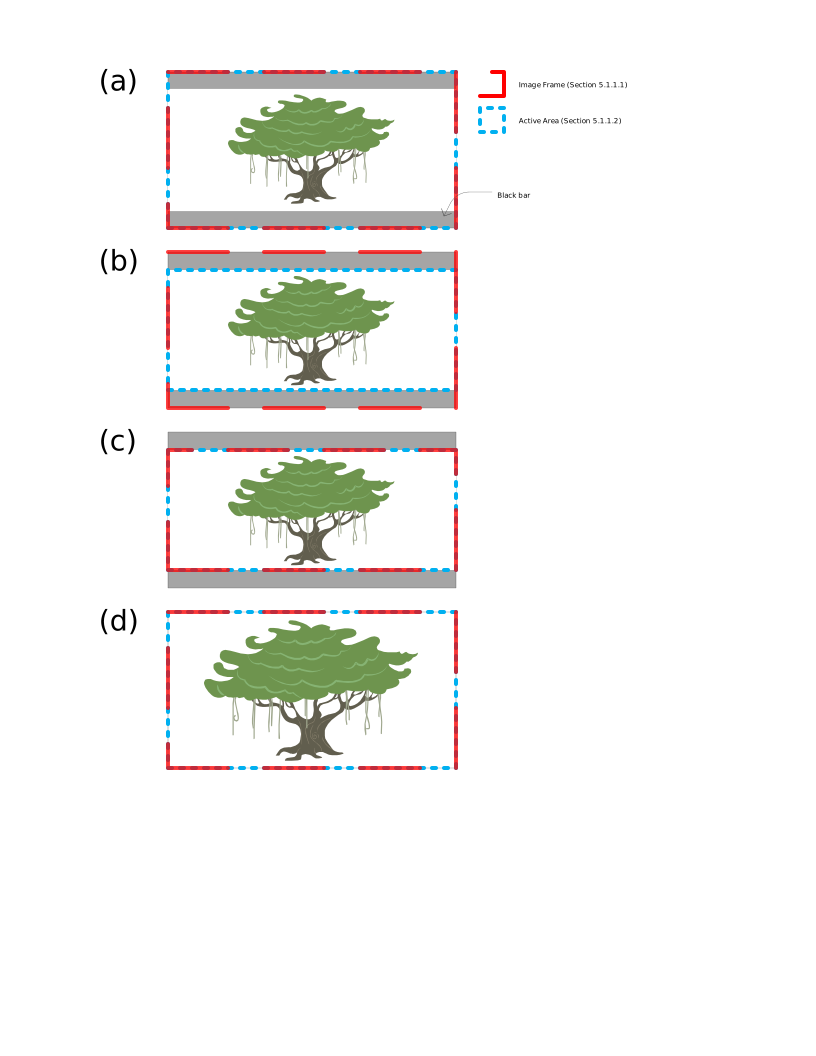
This specification allows the user to choose which rectangular subset of an input image to store and which portion of the resulting stored image to identify as the Active Area Rectangle.
Figure G.1 and Table G.1 depict selected examples using HD progressive image frames. As shown in (a) and (b), two different users or the same user in different circumstances can elect to identify different portions of the same image as the Active Area Rectangle. In (c), only the Active Area Rectangle is stored. As illustrated by (b), the extent of the Display Rectangle is not specified and left to users: Table G.1 lists two valid sets of Display Rectangle and Active Area Rectangle values for (b).
The process by which the dimensions of the stored image and active area are set depends on individual workflows and can include a combination of manual and automated processing during and after ingest.
Figure G.1 — High-Definition Progressive Frame Active Area Rectangle Examples🔗
Table G.1 — Selected Property Values for the Examples of Figure G.1🔗
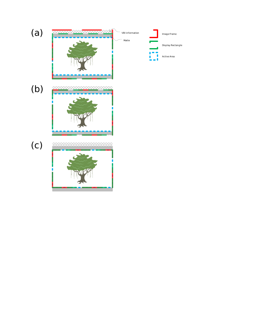
Figure G.2 and Table G.2 depict three means of storing the same source SD interlaced anamorphic image frame. The source image frame contains a 720x576 container as well as vertical blanking interval (VBI) information. The container is intended to be displayed at a 16:9 aspect ratio and contains a 2.40 Active Area Rectangle. In (a), the entire source image frame is ingested, including VBI information, which is not included in the Display Rectangle, as specified by SMPTE ST 377-1:2011. In contrast to (a), the VBI information is not stored in (b). In (c), the Aspect Ratio property value is computed to preserve the exact pixel aspect ratio of the source image.
Figure G.2 — Standard Definition Interlaced Frame Examples🔗
Table G.2 — Selected Property Values for the Examples of Figure G.2🔗
Bits of Ccap15 corresponding to the selected constrained codestream sets must be set.
Bits 14-15 of Ccap15 shall be zero (HTONLY)
Bit 13 of Ccap15 shall be zero (SINGLEHT)
Bit 12 of Ccap15 shall be zero (RGNFREE)
Bit 11 of Ccap15 shall be zero (HOMOGENEOUS)
Bits 0-4 of Ccap15 shall be set according to the MAGBP parameter
Bit 5 of Ccap15 shall be zero (HTREV)
Bit 5 of Ccap15 shall be one (HTIRV)
Tile
One tile for the whole image, with
YTsiz + YTOsiz ≥ Ysiz
XTsiz + XTOsiz ≥ Xsiz
Image and tile origin
XOsiz = YOsiz = XTOsiz = YTOsiz = 0
Sub-sampling
(XRsizi = 1 for all i) or (Xrsizi=2 for i = {2,3} and XRsizi=1 for other i)
YRsizi=1 for all i
Number of components
Csiz ≤ 4
Bitdepth
7 ≤ Ssizi ≤ 15
Within a codestream, all components shall have identical Ssizi
PPM marker
Shall not be present
Number of layers
Shall be exactly 1
Number of decomposition levels
1 ≤ NL ≤ 5 for max(Xsiz,Ysiz) ≤ 2048
1 ≤ NL ≤ 6 for 2049 ≤ max(Xsiz,Ysiz) ≤ 4096
1 ≤ NL ≤ 7 for 4097 ≤ max(Xsiz,Ysiz) ≤ 8192
Within a codestream, all components shall have the same number of decomposition levels
Code-block size
5 ≤ xcb ≤ 7 and 5 ≤ ycb ≤ 6
Within a codestream, all components shall have identical codeblock sizes.
Code-block style
0100 0000
Transformation
5-3 reversible transform
9-7 irreversible transform
Precinct size
PPx = PPy = 7 for NLLL band, else 8
Progression order
RPCL
Tile-parts
one tile part per resolution
TLM marker
Shall be present
POC marker
Shall not be present
Constrained codestream sets
Shall belong to the following sets:
HTONLY, SINGLEHT, RGNFREE, HOMOGENEOUS, LOCAL
HTREV
MAGBP per parameter B calculated according to Table H.2
HTIRV
MAGBP per parameter B shall be equal to or less than 31
MAGBP per parameter B should be equal to or less than the values calculated according to Table H.3
Table H.2 — Parameter B for APP2.HT.REV Constraints🔗
Ssizi
Parameter B
SGcod.C = 0
NL ≤ 5
SGcod.C = 0
NL > 5
SGcod.C = 1
NL > 5
SGcod.C = 1
NL ≤ 5
7
11
12
13
9
13
14
15
11
15
16
17
15
19
20
21
Table H.3 — Parameter B for APP2.HT.IRV Constraints🔗
Parameter B
Ssizi
SGcod.C = 0
SGcod.C = 1
7
9
9
9
11
11
11
13
14
15
17
18
NOTE 1 — As specified at ISO/IEC 15444-1:2019, SGcod.C indicates whether the multiple component transformation is used.🔗
NOTE 2 — Table 4 at ISO/IEC 15444-15:2019 specifies the relationship between parameter B and MAGBP codestream sets.🔗
NOTE 3 — Using RPCL progression order allows reduced-resolution decoding of codestreams in throughput-limited and -varying environments with a single contiguous read operation of a partial codestream.🔗
NOTE 4 — Conformance to the constrained codestream set LOCAL is implied by the signaling of other HTJ2K constraints Precinct Size = [PPx = PPy = 7 for NLLL band, else 8] and Number of layers = 1🔗
NOTE 5 — A decoder can increase throughput by using a hardware-accelerated implementation if the HT cleanup magnitudes are below a given threshold, i.e., if the HTJ2K codestream belongs to a set where parameter B is below a certain threshold; and reverting to a slower software implementation otherwise. Thus HTJ2K encoders are encouraged to use a value of parameter B that is as small as possible, like those values described in Table H.3🔗
Example encoder commands that generate JPEG 2000 Part-15 (HTJ2K) codestreams that satisfy these constraints are included in Annex I.
Annex I Example JPEG 2000 encoder commands (Informative)🔗
The tables in this Annex contain example encoder commands that generate compressed JPEG 2000 codestreams. In the examples, the filename represented by ${INPUT_TIF_FILE} is a 16bit TIF file.
The examples were generated with the most current version of each encoder library available at the time of publication and these versions are listed in the caption of each table.
OpenJPEG is an open-source library that supports encoding JPEG 2000 Part-1 codestreams and decoding JPEG 200 Part-1 and JPEG 2000 Part-15 (HTJ2K) codestreams.
Table I.4 — Example JPEG 2000 Part-1 encoder commands for OpenJPEG demo app opj_compress version 2.5.3🔗